안녕하세요?
원룸 나와 살면서 조명을 리모컨으로 켜고 끄게 만들어놓고 살았었는데요.
1년전부터 목소리로 켜고 끌 수 있게 꼭 해야지!! 라고 생각하고 귀찮아서 계속 안하고 있었어요.
그러다가 저번주 주말하고 이번주 주말에 이사온 새 집에 하고 싶다는 욕구가 샘솟아서 대충 한번 만들어 봤어요.
목소리로 조명 켜고 끄는거 영화에서만 되는게 아니라, 값싸고 쉽게 만들수 있으니 하고 싶으신 분들은 한번 만들어보세요.
재밌게 봐주시고 필요한 분들께 도움이 되면 좋겠습니다.
제작기는 네이버 블로그의 글을 그대로 가져왔습니다.
http://blog.naver.com/bumhee34/220666304342
====================네이버 블로그 제작기 시작===========================
안녕하세요?
블로그에 글 올리는 주기가 너무 길다보니 지난번에 그냥 대충 음성인식으로 조명 켜고 끄는 결과만 간략하게 올렸습니다.
감기때문에 몸이 말이 아니지만 집에서 심심해서 케이스 빼고 일단 완성해봤습니다.
다른분들도 따라 할 수 있도록, 나름 상세하게 방법을 적어보도록 할게요.
우선 지난번 결과 포스팅은 아래 링크를 따라 가시면 됩니다!
http://blog.naver.com/bumhee34/220660574101
제작기 시작하기전에 완성된 모습부터 보여드릴게요.
그냥 선을 막 연결해서 사진은 별로 안이쁘니깐, 조명 컨트롤하는 동영상 두편 올릴게요.
목소리는 양해부탁드립니다...ㅎㅎ
우선 책상쪽 의자에 앉아서 제가 컨트롤 할 수 있는 모든 조명을 컨트롤 해봤습니다.
마이크는 손에 들고 테스트 했습니다.
중간에 "아두이노"를 부르는데, 원치않는 상황에서 조명이 반응하지 않도록하기 위해서 그렇게 만들어놨습니다.
아두이노를 부르고 30초 안에 조명을 불러야합니다.
30초면 상당히 넉넉한데 그냥 마음이 조급해서 중간에 한번씩 불렀네요 ㅋㅋ
두번째는 침대에 누워서 조명을 컨트롤 해본것입니다.
아두이노랑 모듈들은 침대 헤드에 놓고 테스트 해봤습니다.
이제 조명을 끄기위해 움직이지 않아도 되고, 리모컨을 찾지 않아도 됩니다 ㅋㅋ
누워서 소리를 질러서 그런지 목소리가 삑살날뻔했습니다.
자 시작해 봅시다.
우선, 집안의 조명들을 RF 스위치로 컨트롤 할 수 있게 바꿔놓은 상황입니다.
관련된건 원룸 DIY 포스팅들을 참조해주세요.
원리는 다음과 같습니다.
전체 구성 : 아두이노 + RF 모듈 (315/433 MHz) + 음성인식 모듈
1. RF 모듈을 사용하여, RF 리모컨들의 RF 신호를 decode 한뒤 정보를 저장해놓습니다.
2. 음성인식 모듈에 목소리를 몇가지 저장해 놓습니다.
3. 특정 목소리를 인식하면, RF 모듈에서 저장해놓은 RF 신호를 쏴줍니다.
원리는 간단합니다.
그리고 요즘 아두이노 관련된 library들 및 예제가 너무 상세하게 많아서 조금만 검색하면 원하는걸 금새 구현할 수 있습니다.
준비물입니다.
우선 Arduino Uno 보드를 준비합니다.
아두이노 자체에 큰 코드를 넣을 것이 아니기 때문에 Uno 보다 더 값싼걸 써도 됩니다.
제 경우엔 그냥 방 서랍을 열어보니, 우노랑 메가가 있어서 그냥 우노를 선택했습니다.

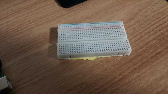
다음은 빵판입니다.
얘도 서랍에 있어서 하나 꺼내썼습니다.
다 만들고 전원부 라인부만 뜯은 상태로 사진을 찍어서 좀 모양새가 떨어지네요.
빵판없이 그냥 직접 라인을 다 연결하셔도 됩니다.
그치만 빵판이 있으면 편하겠죠?
다음은 음성인식모듈입니다.
Voice Recognition module로 검색하시면 바로 나옵니다.

그치만 검색하기도 귀찮으신 분들을 위해서 링크 걸어드릴게요.
http://www.elechouse.com/elechouse/index.php?main_page=product_info&cPath=168_170&products_id=2254
위 링크 가시면, 매뉴얼 및 library를 받을 수 있습니다.
물론 친절하게도 GitHub에도 올라가 있으니 Git쓰시는게 편하신분들은 clone해다가 쓰세요.
https://github.com/elechouse/VoiceRecognitionV3.git
다음은 RF 모듈입니다.
사진상에서 왼쪽편이 신호를 받는 모듈이고, 오른쪽편이 내보내는 모듈입니다.
RF 관련 library들은 몇가지가 있으니 취향에 맞게 골라 쓰시면 됩니다.
저는 어쩔수없이 좋은 library를 사용하지 못하고... ScottC라는 분이 올린 코드를 활용하였습니다.

RF 관련 좋은 library는 rc-switch library가 있습니다.
상기 라이브러리를 사용하면, RF 시그널 decode가 상당히 쉽습니다.
근데 좋은데 전 못썼습니다...
이유는 상기 라이브러리가 decode가능한 칩셋이 아래의 종류로 한정이 되있습니다.
- SC5262 / SC5272
- HX2262 / HX2272
- PT2262 / PT2272
- EV1527 / RT1527 / FP1527 / HS1527
- Intertechno outlets
왠만한거는 다 된다고 보면 되는데, 제가 가진 중국의 RF 스위치 리모컨은 안되더라고요.
우선 리모컨의 생김새는 아래와 같습니다.
이 리모컨으로 조명이 컨트롤되게 모든 스위치를 다 바꿔놨습니다.
아참, 주파수는 433 MHz 입니다.

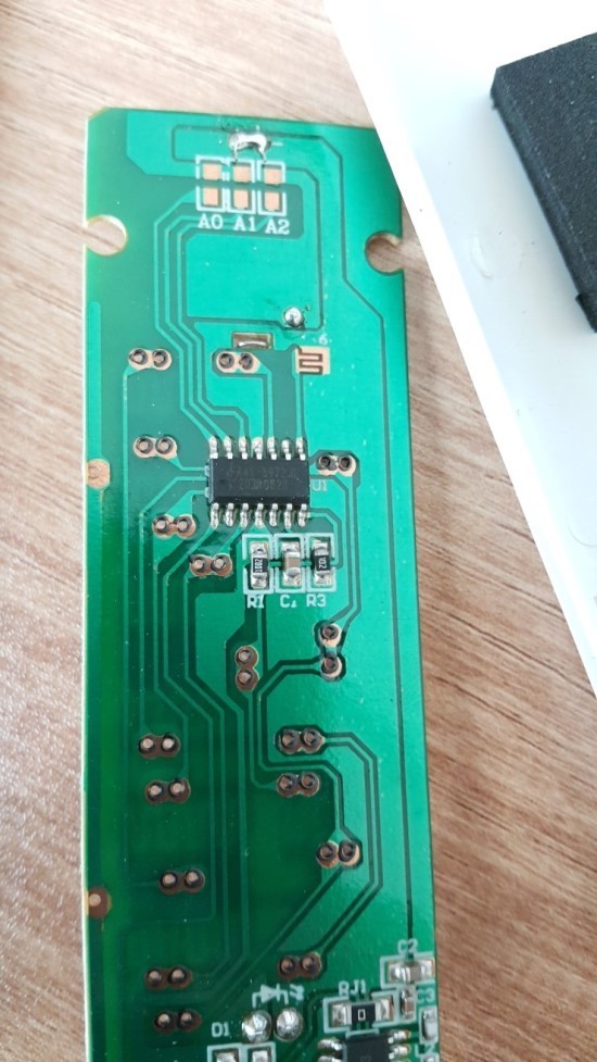
쉽게 뜯을 수 있습니다.
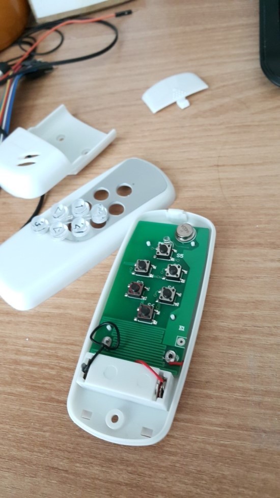
뒷면을 보면, 칩셋이 보이는데 보통 저곳에 칩셋명이 써있는데 아예 아무런 문구가 없습니다 ㅋㅋ
rc-switch library 인식하면 좋았을텐데... 아쉽게도 인식을 안하네요 ㅠㅠ

다음것은 아래의 리모컨입니다.
얘도 433 MHz 주파수를 가지고 있고, 콘센트를 켰다 껐다 컨트롤 할 수 있습니다.
관련된 포스팅도 링크를 걸어놓을게요.
근데 이 리모컨과 무선콘센트 세트는 중국에서 구매했었는데 이제는 구매할 방법이 없네요 ㅠㅠ
http://blog.naver.com/bumhee34/220282513688

암튼 이 리모컨은 뜯으면 칩셋이 나와있고, rc-switch library로 인식하지만,
그냥 코드의 통일성을 위해서 ScottC의 방법을 이용해보도록 할게요.
우선 아래의 코드가 필요합니다.
무엇을 하는 코드냐면, RF 모듈에서 들어오는 analog신호를 분석하는 코드 입니다.
그러다보니 약간의 노가다가 필요합니다...
원리의 상세한설명은 스콧씨의 블로그에 잘 나와있으니 설명을 생략합시다.
코드는 ScottC의 블로그에서 가져왔습니다. (http://arduinobasics.blogspot.kr/2014/06/433-mhz-rf-module-with-arduino-tutorial_27.html)
사람마다 아두이노에 업로드 하는 방법이 다를텐데, 저는 platformio를 사용해서 9번째 줄에 Arduino.h를 추가해 줬습니다.
-
RF Remote Capture sketch
Written by ScottC 24 Jun 2014
Arduino IDE version 1.0.5
Website: http://arduinobasics.blogspot.com
Receiver: XY-MK-5V
Description: Use Arduino to Receive RF Remote signal
------------------------------------------------------------
#include <Arduino.h> // for platformio
const int dataSize = 500; //Arduino memory is limited (max=1700)
byte storedData[dataSize]; //Create an array to store the data
#define ledPin 13 //Onboard LED = digital pin 13
#define rfReceivePin A0 //RF Receiver data pin = Analog pin 0
const unsigned int upperThreshold = 100; //upper threshold value
const unsigned int lowerThreshold = 80; //lower threshold value
int maxSignalLength = 255; //Set the maximum length of the signal
int dataCounter = 0; //Variable to measure the length of the signal
unsigned long startTime=0; //Variable to record the start time
unsigned long endTime=0; //Variable to record the end time
unsigned long signalDuration=0; //Variable to record signal reading time
void setup(){
Serial.begin(9600);
pinMode(ledPin, OUTPUT);
- The following code will only run ONCE --------------
---Press the reset button on the Arduino to run again-
while(analogRead(rfReceivePin)<1){
//Wait here until a LOW signal is received
startTime=micros(); //Update start time with every cycle.
}
digitalWrite(ledPin, HIGH); //Turn LED ON
//Read and store the rest of the signal into the storedData array
for(int i=0; i<dataSize; i=i+2){
//Identify the length of the LOW signal---------------LOW
dataCounter=0; //reset the counter
while(analogRead(rfReceivePin)>upperThreshold && dataCounter<maxSignalLength){
dataCounter++;
}
storedData[i]=dataCounter;
//Identify the length of the HIGH signal---------------HIGH
dataCounter=0;//reset the counter
while(analogRead(rfReceivePin)<lowerThreshold && dataCounter<maxSignalLength){
dataCounter++;
}
storedData[i+1]=dataCounter;
//Any readings between the two threshold values will be ignored.
//The LOW or HIGH signal length must be less than the variable "maxSignalLength"
//otherwise it will be truncated. All of the HIGH signals and LOW signals combined
//must not exceed the variable "dataSize", otherwise it will be truncated.
//The maximum number of signals is 1700 - if you try to extend this variable to a higher
//number than 1700 - then the Arduino will freeze up and sketch will not work.
//-------------------------------------------------------------
}
endTime=micros(); //Record the end time of the read period.
signalDuration = endTime-startTime;
digitalWrite(ledPin, LOW);//Turn LED OFF
//Send report to the Serial Monitor
Serial.println("=====================");
Serial.print("Read duration: ");
Serial.print(signalDuration);
Serial.println(" microseconds");
Serial.println("=====================");
Serial.println("LOW,HIGH");
delay(20);
for(int i=0; i<dataSize; i=i+2){
Serial.print(storedData[i]);
Serial.print(",");
Serial.println(storedData[i+1]);
delay(20);
}
}
void loop(){
//Do nothing here
}
어찌됐건 상기 코드를 아두이노에 올린뒤에, decode하고 싶은 리모컨 버튼을 눌러줍니다.
누른 상태에서 아두이노의 reset 버튼을 누르면 시리얼 모니터에서 다음과 같이 LOW, HIGH 시그널로 구분되어 나오는 신호를 볼수 있습니다.

250개의 데이터가 나올 텐데요.
그것을 엑셀로 복사합시다!
우선 Low signal을 분석해보면 아래와 같이 1,2에 집중이 되어 있고, 6,7에 집중이 되어 있습니다.
원래는 두개로 나뉜다고 봐야하는데, 아날로그를 대충 역치를 줘서 분석하다보니 저렇게 나옵니다.
이 경우는 2, 6 으로 나눠서 테스트를 해보고 잘 됐음을 확인하였습니다.

마찬가지로 High signal도 정리를 해보면, 얘는 크게 3가지 그룹으로 나눠지는걸 알 수 있습니다.
얘도 애매하게 3그룹이여서 코드를 슬쩍슬쩍 수정하면서 테스트를 하여야합니다.

재정리를 해봅시다.
여기부터는 아트가 시작됩니다.
Low signal은 3기준으로 아래에 있는것은 0으로 두고 위에 있는것은 1로 둬서 정렬을 해봅시다.
사진상에서는 잘 안보이지만 일정한 패턴으로 신호가 나가는걸 알 수 있습니다.

마찬가지로 High signal도 정리를 해서 총 3개의 그룹으로 나눕니다.
얘도 특정 패턴이 있습니다.
그리고 제일 높은 값의 주기가 신호의 주기와 동일합니다.
제가 가진 리모컨들은 모두 주기가 25네요.
25번마다 동일한 신호가 나가는걸 알 수 있습니다.

그리고 이 부분이 재밌는 부분이에요.
Low signal은 두 종류 이며 상기 예시에서는 (2,6), 재정렬은 0,1로 맞췄으며
High signal은 세 종류 이며 (3,7,54), 재정렬은 0,1,2로 맞췄습니다.
상기의 예시에서 (2,6)보다 (1,7)이 더 잘동작할수도 있으며 (3,7,54)도 마찬기지로 (3,7,55)등이 더 잘동작할 수 있습니다.
잘 동작하는걸 찾는게 노가다 입니다.
아무튼 Low 두 종류 High 세 종류로 나눠지니깐 총 6개의 그룹이 생성됩니다.
ScottC의 용어를 그대로 빌려와서 설명을 하겠습니다.
아래의 6개의 그룹을 다시 엑셀로 정렬 해 봅시다.
Low signal
High signal
Pattern group
0 (Short Low, SL)
실제값 1 or 2
0 (Short High, SH)
실제값 2 or 3
1
0 (Short Low, SL)
실제값 1 or 2
1 (Long High, LH)
실제값 6 or 7
2
0 (Short Low, SL)
실제값 1 or 2
2 (Very Long High, VLH)
실제값 54 or 55
3
1 (Long Low, LL)
실제값 6 or 7
0 (Short High, SH)
실제값 2 or 3
4
1 (Long Low, LL)
실제값 6 or 7
1 (Long High, LH)
실제값 6 or 7
5
1 (Long Low, LL)
실제값 6 or 7
2 (Very Long High, VLH)
실제값 54 or 55
6
그럼 아래와 같이 정리가 되고,

좀 확대해 봅시다.
화살표로 표시한 부분이 신호의 주기 입니다.
앞서 설명한 High signal의 최고값의 주기와 동일합니다.
아래의 예시에서는 패턴의 값이 {5,2,1,5,1,5,2,2,2,2,2,1,4,5,2,2,2,2,2,2,2,2,2,1,6} 나오는걸 알수있습니다.

이제 상기 패턴을 사용하여서, 다시 신호를 내보낼 차례 입니다.
처음값인 5를 내보낸다고 하면, 5에 해당하는 LL과 LH의 실제 신호값을 디지털값으로 RF 송신기에 쏴서 보내면 됩니다.
상기 예제에서는 LL은 2, LH는 7 정도가 되겠네요.
아참 이것뿐만이 아니라 각 단위 신호의 time delay 값도 찾는 노가다가 필요합니다.
이런 노가다를 아래의 코드를 사용해서 하면 됩니다.
아래의 코드에서 예를 들면, 15번과 16번에 on/off RF 신호 패턴을 넣어주고,
19줄의 timeDelay를 10 micro seconds 부터 시작해서 조금씩 늘려주도록 합시다.
그리고 65~88줄까지 각각 RF 신호 패턴에 해당되는 low signal과 high signal의 실제 신호값이라 추정되는 값들을 넣어줍시다.
그리고 코드를 돌리고 serial monitor로 지켜보고 있으면, 특정 timeDelay 구간에서 조명이 켜졌다 꺼졌다하는걸 볼 수 있습니다.
그걸 모든 리모컨 버튼에 대해서 다 기록을 해 둡시다.
-
433 MHz RF REMOTE REPLAY sketch
Written by ScottC 24 Jul 2014
Arduino IDE version 1.0.5
Website: http://arduinobasics.blogspot.com
Receiver: XY-MK-5V Transmitter: FS1000A/XY-FST
Description: Use Arduino to receive and transmit RF Remote signal
------------------------------------------------------------
#include <Arduino.h>
#define rfTransmitPin 4 //RF Transmitter pin = digital pin 4
#define ledPin 13 //Onboard LED = digital pin 13
const int codeSize = 25; //The size of the code to transmit
int codeToTransmit[codeSize]; //The array used to hold the RF code
int lightON[]= {5,2,1,5,1,5,2,2,2,2,2,1,4,5,2,2,2,2,2,2,2,2,2,1,6}; //The RF code that will turn the light ON
int lightOFF[]= {5,2,1,5,1,5,2,2,2,2,2,1,4,5,2,2,2,2,2,2,2,2,2,1,6};
//The RF code that will turn the light OFF
int codeToggler = 0; //Used to switch between turning the light ON and OFF
int timeDelay=10; // The variable used to calibrate the RF signal lengths.
-----------------------------------------------------------------
toggleCode(): This is used to toggle the code for turning
the light ON and OFF
------------------------------------------------------------------
void toggleCode(){
if(codeToggler){
for(int i = 0; i<codeSize; i++){
codeToTransmit[i]=lightON[i];
}
} else{
for(int i = 0; i<codeSize; i++){
codeToTransmit[i]=lightOFF[i];
}
}
codeToggler=!codeToggler;
}
------------------------------------------------------------------
transmitCode(): Used to transmit the signal to the RF receiver on
the fan/light. There are 6 different HIGH-LOW signal combinations.
SH = short high or LH = long high
PLUS
SL = short low or LL = long low or VLL = very long low
--------------------------------------------------------------------
void transmitCode(){
// The LED will be turned on to create a visual signal transmission indicator.
digitalWrite(ledPin, HIGH);
//initialise the variables
int highLength = 0;
int lowLength = 0;
//The signal is transmitted 6 times in succession - this may vary with your remote.
for(int j = 0; j<7; j++){
for(int i = 0; i<codeSize; i++){
switch(codeToTransmit[i]){
case 1: // SH + SL
highLength=2;
lowLength=3;
break;
case 2: // SH + LL
highLength=2;
lowLength=7;
break;
case 3: // SH + VLL
highLength=2;
lowLength=54;
break;
case 4: // LH + SL
highLength=6;
lowLength=3;
break;
case 5: // LH + LL
highLength=6;
lowLength=7;
break;
case 6: // LH + VLL
highLength=6;
lowLength=54;
break;
}
- Transmit a HIGH signal - the duration of transmission will be determined
by the highLength and timeDelay variables -
digitalWrite(rfTransmitPin, HIGH);
delayMicroseconds(highLength*timeDelay);
- Transmit a LOW signal - the duration of transmission will be determined
by the lowLength and timeDelay variables -
digitalWrite(rfTransmitPin,LOW);
delayMicroseconds(lowLength*timeDelay);
}
}
//Turn the LED off after the code has been transmitted.
digitalWrite(ledPin, LOW);
}
void setup(){
Serial.begin(9600); // Turn the Serial Protocol ON
pinMode(rfTransmitPin, OUTPUT); //Transmit pin is an output
pinMode(ledPin, OUTPUT);
//LED initialisation sequence - gives us some time to get ready
digitalWrite(ledPin, HIGH);
delay(1000);
digitalWrite(ledPin, LOW);
delay(1000);
}
void loop(){
toggleCode(); // switch between light ON and light OFF
transmitCode(); // transmit the code to RF receiver on the Fan/Light
timeDelay+=10; //Increment the timeDelay by 10 microseconds with every transmission
Serial.println(timeDelay);
delay(1000); //Each transmission will be about 2 seconds apart.
}
아이고 뭐 이리 길어....상세히 쓰겠다고 했는데..점점 졸려집니다....
아무튼, 이제 음성인식모듈을 사용하여서 원하는 목소리를 녹음해봅시다.
코드가 길어서 여기에 쓰진 않고, elechouse의 GitHub에 올라와있으니 링크로 대체 합니다.
아래의 코드를 아두이노에 업로드 한뒤에,
https://github.com/elechouse/VoiceRecognitionV3/blob/master/examples/vr_sample_train/vr_sample_train.ino
시리얼 모니터로 명령어를 줘서 녹음을 하면 됩니다.
예를 들어서 스크린에 있는 조명을 껐다 켰다하기위해서 스크린이라는 명령어를 녹음할 겁니다.
그러면 "sigtrain 녹음하고자하는번호 comment"로 명령어를 치면 Speak now라고 화면에 뜹니다.
그때 열심히 마이크에 대고 속삭이면 됩니다.
그리고 나서 load기능으로 녹음해둔 목소리를 사용데이터군에 집어넣습니다.
자세한 설명은 매뉴얼에 있으니 생략할게요.
글이 길어지니 점점 지칩니다.

거의 다 되었습니다.
정리 해볼까요?
1. ScottC의 코드로 RF 시그널을 decode하여서 데이터를 정리하였다.
2. 정리된 데이터를 가지고 노가다를 하면서 조명이 켜고 꺼지는 low signal, high signal 및 time delay를 찾았다.
3. 음성인식모듈에 목소리를 녹음해두고, load 해두었다.
자 이제는 그것을 조합해서 코드를 짜면 됩니다.
특정 목소리가 나오면, 특정 RF 신호가 나가도록 하면 되죠.
ScottC의 코드와 elechouse의 코드를 참조하여 간단한 코드를 만들었습니다.
급하게 대충 만들었지만 원하시는대로 수정해서 쓸 수 있을 정도는 될거에요.
코드의 기능을 간략하게 설명할게요.
1. 저장된 목소리에 해당하는 RF 시그널을 쏘아 보낸다.
2. ArduinoCall이라고 저장된 목소리에 아두이노가 반응한다.
3. 아두이노가 반응하고 30초 이내에 원하는 조명을 말해야한다. (30초 이내에는 몇번이고 가능)StopWatch library를 사용하였다.
4. 30초가 지나면 아두이노를 다시 반응시켜야만 조명을 켤 수 있다.
5. 목소리 데이터를 7개까지밖에 사용 못하기에, on/off 시그널로 나눠지는 시그널은 toggle 기능을 사용하였다. 즉, on다음엔 무조건 off, off 다음엔 무조건 on이 되게 하였다. 이때문에 특정 상황에서는 조명을 두번 불러야 반응을 한다. (손으로 직접 켜고 껐을 경우)
- RF signal control with Voice Recognition module |
Skeleton sketch, version 0.1 |
|
Feel free to talk |
bumhee34@kaist.ac.kr |
bumhee34@gmail.com, |
bumhee34@naver.com, |
|
2016/03/26 -
-=====================================================!!
This code is the modification of the following two codes,
1. vr_sample_control_led.ino from VoiceRecognition Library
2. 433 MHz RF REMOTE REPLAY sketch
Written by ScottC 24 Jul 2014
Arduino IDE version 1.0.5
Website: http://arduinobasics.blogspot.com
=========================================================-
#include <Arduino.h> // When you use something like platformio, then include this one
#include <VoiceRecognitionV3.h> //VR
#include <StopWatch.h>
StopWatch SW;
// VR module settings
VR myVR(8,9); // 8:TX 9:RX, !! Depends on users
uint8_t bufInit[64], bufLoop[64];
int ledPin = 13;
int selectLight;
- Following lines depend on users, total 7 voice calls can be used. -
#define ArduinoCall (0)
#define ScreenLight (1)
#define BedLight (2)
#define HallwayLight (3)
#define CeilingLight (4)
#define BathroomLight (5)
#define KitchenLight (6)
// RF module settings
#define rfTransmitPin 4 //RF Transmitter pin !! Depends on users
const int codeSize = 25; //The size of the code to transmit
int codeToTransmit[codeSize]; //The array used to hold the RF code
// Followings are decoded RF signals,
// toggle is used for on/off case due to the limitation of voice recognition module
// decoding can be done by the code from ScottC,http://arduinobasics.blogspot.com
int ScreenRF_On[]={3,4,2,2,2,4,4,4,2,2,2,4,4,2,4,4,2,2,2,2,2,2,4,2,4};
int ScreenRF_Off[]={4,2,2,2,4,4,4,2,2,2,4,4,2,4,4,2,2,2,2,2,2,4,4,4,3};
int ScreenHighLength[]={2,6}; // short, long
int ScreenLowLength[]={2,6,78}; // short, long, very long
int ScreenTimeDelay=100;
int BedRF_On[]={3,4,2,2,2,4,4,4,2,2,2,4,4,2,4,4,2,2,2,2,2,4,2,2,2};
int BedRF_Off[]={4,2,2,2,4,4,4,2,2,2,4,4,2,4,4,2,2,2,2,2,2,4,4,2,3};
int BedHighLength[]={2,6};
int BedLowLength[]={2,6,78};
int BedTimeDelay=100;
int HallwayRF[]={5,2,1,5,1,5,2,2,2,2,2,1,4,5,2,2,2,2,2,2,2,1,4,4,6};
int HallwayHighLength[]={2,6};
int HallwayLowLength[]={3,7,55};
int HallwayTimeDelay=120;
int CeilingRF[]={5,2,1,5,1,5,2,2,2,2,2,1,4,5,2,2,2,2,2,2,2,2,2,1,6};
int CeilingHighLength[]={2,6};
int CeilingLowLength[]={3,7,54};
int CeilingTimeDelay=120;
int BathroomRF[]={5,2,1,5,1,5,2,2,2,2,2,1,4,5,2,2,2,2,2,2,2,1,5,1,6};
int BathroomHighLength[]={2,6};
int BathroomLowLength[]={3,7,54};
int BathroomTimeDelay=120;
int KitchenRF[]={5,2,1,5,1,5,2,2,2,2,2,1,4,5,2,2,2,2,2,2,1,5,1,4,6};
int KitchenHighLength[]={2,6};
int KitchenLowLength[]={3,7,55};
int KitchenTimeDelay=120;
int HighLength[2], LowLength[3];
int timeDelay; // The variable used to calibrate the RF signal lengths.
int codeToggler = 0; //Used to switch between turning the light ON and OFF
- Small modules are listed -
void toggleCode(){
// only for on/off swtich
if(selectLight==1 || selectLight==2){
if(codeToggler){
for(int i = 0; i<codeSize; i++){
if(selectLight==1) codeToTransmit[i]=ScreenRF_On[i];
if(selectLight==2) codeToTransmit[i]=BedRF_On[i];
}
}else{
for(int i = 0; i<codeSize; i++){
if(selectLight==1) codeToTransmit[i]=ScreenRF_Off[i];
if(selectLight==2) codeToTransmit[i]=BedRF_Off[i];
}
}
codeToggler=!codeToggler;
}
// non on/off switch
for(int i=0; i<codeSize; i++){
switch(selectLight){
case 3: // Hallway
codeToTransmit[i]=HallwayRF[i];
break;
case 4: // Ceiling
codeToTransmit[i]=CeilingRF[i];
break;
case 5: // Bathroom
codeToTransmit[i]=BathroomRF[i];
break;
case 6: // Kitchen
codeToTransmit[i]=KitchenRF[i];
break;
}
}
}
- select RF length and time delay to calibrate RF signals -
void selectLength(){
// Select high length & time delay
for(int i=0; i<3; i++){
switch(selectLight){
case 1:
if(i!=2) HighLength[i]=ScreenHighLength[i];
LowLength[i]=ScreenLowLength[i];
if(i==0) timeDelay=ScreenTimeDelay;
case 2:
if(i!=2) HighLength[i]=BedHighLength[i];
LowLength[i]=BedLowLength[i];
if(i==0) timeDelay=BedTimeDelay;
case 3:
if(i!=2) HighLength[i]=HallwayHighLength[i];
LowLength[i]=HallwayLowLength[i];
if(i==0) timeDelay=HallwayTimeDelay;
case 4:
if(i!=2) HighLength[i]=CeilingHighLength[i];
LowLength[i]=CeilingLowLength[i];
if(i==0) timeDelay=CeilingTimeDelay;
case 5:
if(i!=2) HighLength[i]=BathroomHighLength[i];
LowLength[i]=BathroomLowLength[i];
if(i==0) timeDelay=BathroomTimeDelay;
case 6:
if(i!=2) HighLength[i]=KitchenHighLength[i];
LowLength[i]=KitchenLowLength[i];
if(i==0) timeDelay=KitchenTimeDelay;
}
}
}
- Send RF signals -
void transmitCode(){
// The LED will be turned on to create a visual signal transmission indicator.
digitalWrite(ledPin, HIGH);
//local variables
int highLength = 0;
int lowLength = 0;
// The signal is transmitted 7 times in succession
// this may vary with your remote.
for(int j = 0; j<7; j++){
for(int i = 0; i<codeSize; i++){
switch(codeToTransmit[i]){
case 1: // SH + SL
highLength=HighLength[0];
lowLength=LowLength[0];
break;
case 2: // SH + LL
highLength=HighLength[0];
lowLength=LowLength[1];
break;
case 3: // SH + VLL
highLength=HighLength[0];
lowLength=LowLength[2];
break;
case 4: // LH + SL
highLength=HighLength[1];
lowLength=LowLength[0];
break;
case 5: // LH + LL
highLength=HighLength[1];
lowLength=LowLength[1];
break;
case 6: // LH + VLL
highLength=HighLength[1];
lowLength=LowLength[2];
break;
}
- Transmit a HIGH signal - the duration of transmission will be determined
by the highLength and timeDelay variables -
digitalWrite(rfTransmitPin, HIGH);
delayMicroseconds(highLength*timeDelay);
- Transmit a LOW signal - the duration of transmission will be determined
by the lowLength and timeDelay variables -
digitalWrite(rfTransmitPin,LOW);
delayMicroseconds(lowLength*timeDelay);
}
}
//Turn the LED off after the code has been transmitted.
digitalWrite(ledPin, LOW);
}
-*
@brief Print signature, if the character is invisible,
print hexible value instead.
@param bufInit --> command length
len --> number of parameters
-
void printSignature(uint8_t *bufInit, int len)
{
int i;
for(i=0; i<len; i++){
if(bufInit[i]>0x19 && bufInit[i]<0x7F){
Serial.write(bufInit[i]);
}
else{
Serial.print("[");
Serial.print(bufInit[i], HEX);
Serial.print("]");
}
}
}
-*
@brief Print signature, if the character is invisible,
print hexible value instead.
@param bufInit --> VR module findVoiceurn value when voice is recognized.
bufInit[0] --> Group mode(FF: None Group, 0x8n: User, 0x0n:System
bufInit[1] --> number of record which is recognized.
bufInit[2] --> Recognizer index(position) value of the recognized record.
bufInit[3] --> Signature length
bufInit[4]~bufInit[n] --> Signature
-
void printVR(uint8_t *bufInit)
{
Serial.println("VR Index Group RecordNum Signature");
Serial.print(bufInit[2], DEC);
Serial.print(" ");
if(bufInit[0] == 0xFF){
Serial.print("NONE");
}
else if(bufInit[0]&0x80){
Serial.print("UG ");
Serial.print(bufInit[0]&(~0x80), DEC);
}
else{
Serial.print("SG ");
Serial.print(bufInit[0], DEC);
}
Serial.print(" ");
Serial.print(bufInit[1], DEC);
Serial.print(" ");
if(bufInit[3]>0){
printSignature(bufInit+4, bufInit[3]);
}
else{
Serial.print("NONE");
}
Serial.println("rn");
}
void setup(){
-* initialize -
myVR.begin(9600);
Serial.begin(9600);
pinMode(ledPin, OUTPUT);
if(myVR.clear() == 0){
Serial.println("Recognizer cleared.");
}else{
Serial.println("Not find VoiceRecognitionModule.");
Serial.println("Please check connection and restart Arduino.");
while(1);
}
// Check voice calls
if(myVR.load((uint8_t)ArduinoCall) >= 0) Serial.println("ArduinoCall loaded");
if(myVR.load((uint8_t)ScreenLight) >= 0) Serial.println("ScreenLight loaded");
if(myVR.load((uint8_t)BedLight) >= 0) Serial.println("BedLight loaded");
if(myVR.load((uint8_t)HallwayLight) >= 0) Serial.println("HallwayLight loaded");
if(myVR.load((uint8_t)CeilingLight) >= 0) Serial.println("CeilingLight loaded");
if(myVR.load((uint8_t)BathroomLight) >= 0) Serial.println("BathroomLight loaded");
if(myVR.load((uint8_t)KitchenLight) >= 0) Serial.println("KitchenLight loaded");
- RF module initialization -
pinMode(rfTransmitPin, OUTPUT); //Transmit pin is an output
//LED initialisation sequence - gives us some time to get ready
digitalWrite(ledPin, HIGH);
delay(1000);
digitalWrite(ledPin, LOW);
delay(1000);
SW.start(); // Once you call "Arduino" (no. 0), you must send some RF signals in 10 seconds.
// After 30 seconds, you must call "Arduino" again.
}
void loop(){
int findArduino=0;
int findVoice=0;
int on-eOfVoice=0;
-
// test shoot
while(1){
selectLight=6;
toggleCode();
selectLength();
transmitCode();
delay(1000);
}
-
findArduino=myVR.recognize(bufInit,50);
if(findArduino>0 && bufInit[1]==ArduinoCall){
SW.reset();
SW.start();
digitalWrite(ledPin, HIGH);
delay(500);
digitalWrite(ledPin, LOW);
}
while(findArduino>0 && bufInit[1]==ArduinoCall){
findVoice = myVR.recognize(bufLoop, 50);
if(findVoice>0){
printVR(bufLoop);
selectLight=0; // non-select
on-eOfVoice=0;
switch(bufLoop[1]){
case ArduinoCall:
on-eOfVoice=0;
SW.reset();
SW.start();
digitalWrite(ledPin, HIGH);
delay(500);
digitalWrite(ledPin, LOW);
break;
case ScreenLight:
selectLight=1;
on-eOfVoice=1;
break;
case BedLight:
selectLight=2;
on-eOfVoice=1;
break;
case HallwayLight:
selectLight=3;
on-eOfVoice=1;
break;
case CeilingLight:
selectLight=4;
on-eOfVoice=1;
break;
case BathroomLight:
selectLight=5;
on-eOfVoice=1;
break;
case KitchenLight:
selectLight=6;
on-eOfVoice=1;
break;
}
if(OneOfVoice==1){
toggleCode();
selectLength();
transmitCode(); // send RF signal
}
}
if(SW.elapsed()>30000) {
findArduino=0;
SW.reset();
SW.start();
}
Serial.println(SW.elapsed());
}
}
다 된거라 생각했지만 아니었습니다.
RF 모듈의 한계상 신호거리가 생각보다 짧습니다.
멀리 있는 조명이 생각보다 반응을 잘 안하더라고요.
안테나를 달아주면 되는데.. aliexpress에서 사서 기다리기가 싫어서 급하게 만들었습니다.
구글에서 433 RF design이라고 검색하면 쉽게 구리선으로 안테나를 만들 수 있다는걸 알 수 있습니다.
이렇게 친절하게..!

diameter 0,8mm 짜리 구리선을 우선 찾아봅시다.
동축케이블을 까보면 0.8mm 짜리 구리선이 들어있는걸 발견 할 수 있습니다.
이걸 요령껏 잘 꺼냅니다.

그 뒤에 직경 5.5mm의 심지같은것이 필요한데, 집에 있는 드라이버 심 하나가 정확하게 5.5mm 였습니다.
이 두개를 사용하여

안테나를 만들 수 있습니다.

완성된 안테나를 모듈에 납땜하고 테스트해보니 신호가 훨씬 잘 전달이 됩니다.
어쩌면 플라시보일지도..

모듈들 다 연결한 모습...

빵판이 너무 쓸데없이 커서 전원선 빵판 부분만 따로 떼어 냈습니다.
그래도 여전히 지저분하네요 ㅋㅋㅋ
케이스는 아크릴로 만들려고 도면 그려서 일단 맡겼습니다.

아....설명할게 또 있네요.
ambilight를 적용한 스크린을 평소에는 간접조명으로 쓰도록 틴지코드를 살짝 수정하였습니다.
우선 ambilight가 적용된 포스팅은 다음에 있습니다.
http://blog.naver.com/bumhee34/220646787924
아무튼 간접조명처럼 활용하게끔하고, 앞서 보여드린 무선 콘센트를 달아서 얘도 목소리로 켜고 끌 수 있게 해놨습니다.
ambilight 기능이 필요할때는 ambibox 소프트웨어를 키면되고 바로 ambilight 기능을 수행하게 됩니다.
반대로 ambibox를 끄면 다시 아래와 같은 간접조명으로 돌아옵니다.

앞에 올렸던 동영상 두편 다시 올리면서 마무리 할게요.
의자 앉아서 모든 조명 테스트.
침대누워서 테스트.
지금 쓰면서 너무 졸려가지고 그만 마무리 해야겠네요.
궁금한거는 질문해주시면 제가 아는 선에서는 최대한 도와드릴게요.
많은 분들이 조명을 목소리로 켜고 끌수있으면 좋겠어요.
영화에서만 되는게 아니에요!
이제 얘는 케이스만 만들고 마무리 지어야겠네요.
그럼 모두 굿밤!
============================================네이버 블로그 제작기 끝=======================================
음성인식 조명 하면서 실직적으로는 아두이노를 처음 써본것이나 다름없는데 정말 사용자 친화적이고 비 전공자들도 아주 쉽게 따라 할 수 있네요.
그리고 사람들이 library를 많이 만들어놔서 코드를 몰라도 대충 조합해서 원하는 코드 짜는것도 무지 쉽네요.
왠지 앞으로 아두이노를 많이 사용할 느낌이 듭니다 ㅋㅋ
쓰다가 졸려가지고 결국엔 상세한 제작기가 되진 못했지만
다들 재밌게 보셨으면 좋겠고, 좋은 주말 되시길 바랍니다.

 인스티즈앱
인스티즈앱